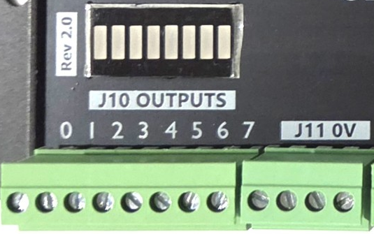
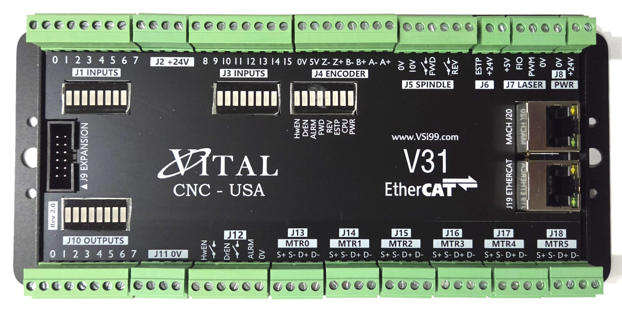
V31 EtherCAT motion controller (Rev 2.0). Use this photo as the connector reference throughout the manual.
The V31 is an industrial-grade motion controller for MachPro CNC systems. It is a stable hardware bridge between your Windows PC and the machine drives. It communicates over Ethernet to keep motion synchronized and precise.
Key features
Axis support: Base support for 6 axes, with scalable license upgrades to 8 or 12 axes.
Control flexibility: Supports EtherCAT and traditional step-and-direction drives, at the same time.
Expandability: Connect EtherCAT I/O modules, absolute encoders and servos so the machine never loses position.
WARNING: Incorrect installation can cause death, injury or equipment damage. Do not install this controller until you have read and understood this manual.
1. Introduction
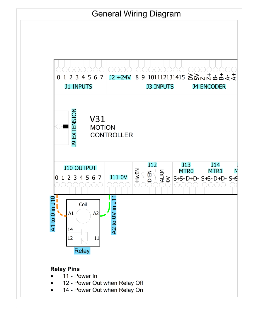
This manual contains several wiring diagrams. Use the board photo above as a reference for connector numbers (J1–J20) throughout the manual.
Connector overview
Connector
Function
Terminals (left to right)
J1
Inputs 0–7
0 1 2 3 4 5 6 7
J2
+24 VDC supply for sensors
+24V ×4
J3
Inputs 8–15
8 9 10 11 12 13 14 15
J4
Encoder (quadrature)
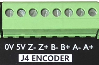
0V 5V Z- Z+ B- B+ A- A+
J5
Spindle
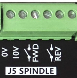
0V, 10V (analog), FWD relay (2), REV relay (2)
J6
Emergency stop
ESTP, +24V
J7
Laser
+5V, FIO, PWM, 0V
J8
Power input
0V, +24V
J9
Expansion header
Ribbon header (pin 1 marked ▲)
J10
Outputs 0–7
0 1 2 3 4 5 6 7
J11
0 V common
0V ×4
J12
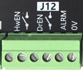
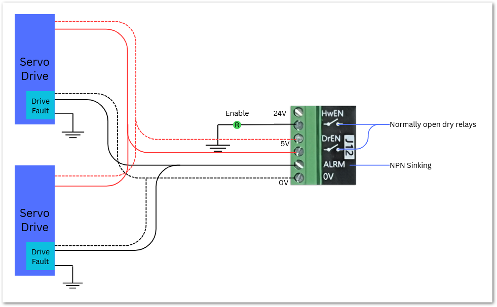
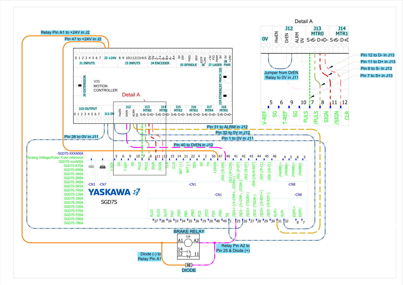
Enable / alarm
HwEN relay (2), DrEN relay (2), ALRM, 0V
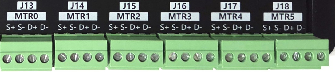
J13–J18
Step/direction, motors 0–5
S+ S- D+ D- (each)
J19
EtherCAT out (RJ45)
To first EtherCAT device
J20
Mach (RJ45)
To the control computer
Specifications
Observe the maximum voltage on each pin. Some pins accept 24 VDC, some 5 VDC, some 3.3 VDC and some are 0 VDC. Exceeding the maximum voltage will seriously damage the V31 motion controller.
Item
Specification
Input Power
24 VDC
Max Power Consumption
48 W
Motor Drives
Stepper Channels
6 motors
Step and Direction Axis Control
5 VDC Single Ended and Differential
Connection
Terminal Blocks
Max Pulse Speed
1.6 MHz
EtherCAT Network
Device Types
Servo Motors, Stepper Motors, VFDs, I/O Modules, etc.
Max Devices
30
Max Motors
6 motors by default (8 and 12 motor options available)
Quadrature Encoder Channel: 1
Connection
Terminal Blocks, 5 VDC Differential
Max Frequency
1.6 MHz
Spindle: 1
Direction Outputs
Forward and Reverse relay dry contacts
Analog Speed Signal
0–10 VDC
Encoder Feedback
Yes
Digital Outputs: 8 (PNP Sourcing)
Voltage
16–24 VDC
Max Current
250 mA
Pulse Width Modulation (PWM)
Not yet available
Inputs: 16 (opto-isolated, for PNP/Sourcing sensors)
Voltage
16–24 VDC
Input Current Range
3–6 mA
Isolated
Yes
Enable Circuits: 2
Hardware Enable
Relay Dry Contacts, 5 VDC Enable or 24 V Enable
Drive Enable
Relay Dry Contacts
Servo Drive Alarm: 1 (NPN Sinking with 24 VDC pull-up)
Voltage
5–24 VDC
Input Current Range
3–6 mA
Other
Emergency Stop Circuit
Normally Closed Connection
Ethernet Port
10/100 Mbps
Dimensions
7.125" (L) × 3.75" (W) × 1.875" (H)
Optimal Temperature Range
32° to 100°F (0° to 38°C)
Humidity
30%–60% RH
Status LEDs
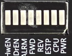
Status LED bar (next to J4)
Each LED has a single color.
LED
ON
OFF
PWR (Power)
Green – V31 is powered
No power
CPU
Blue blinking – V31 CPU is active
Standby mode (blips a little more than once a second)
Run mode (double blip / heartbeat)
Bootloader (rapid flash)
CPU is not enabled
ESTP (E-Stop)
Red – E-Stop pressed, or the E-Stop circuit is incomplete
E-Stop is not active
HwEN (Hardware Enable)
Orange – Hardware Enable is on
No Hardware Enable signal
DrEN (Drive Enable)
Orange – Drive Enable is on
No Drive Enable signal
FWD (Spindle forward)
Green when spinning forward
REV (Spindle reverse)
Green when spinning in reverse
ALRM (Drive Alarm)
Red – One or more drives are in alarm state
All drives report good
Tools required
A small flat-head screwdriver is needed for the I/O terminals.
Recommendations
If your system runs on 480 VAC, we recommend line filters before the servo drives and VFDs to minimize electrical noise from the VFDs.
The V31 motion controller and the drives can supply 24 VDC, but they do not have high current capacity. We recommend adding separate 24 VDC power supplies. Specific suggestions for success:
Use separate 24 VDC supplies for I/O and field loads if current is high.
Tie all 0 V terminals to a single 0 V / ground bar in the main cabinet.
Bond this bar to PE at one place.
Keep motion controller and drive I/O referenced to this same 0 V bar.
Use isolated I/O for external panels and long cables.
This approach prevents large ground potential differences while still offloading the 24 VDC outputs on drives and motion controllers.
Firmware update
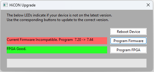
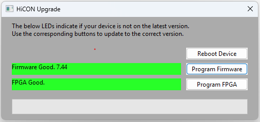
On the first start of MachPro, the software checks that the V31 motion controller has the latest firmware. If not, you will see an update screen, which shows both the current and latest firmware versions.
Follow the prompts to update the V31 firmware. When the process completes, the V31 must reboot, and you will be prompted to approve that. Once the V31 is running again, and both the Firmware and FPGA are current, close the Upgrade window.
The configuration menus are locked while the system is enabled, and all menu options are grayed out. Disable the system to make configuration changes.
Hardware startup (J8)
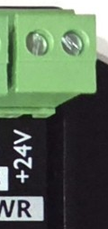
To power the V31, supply 24 VDC to the J8 PWR connector at the top right of the board. The PWR LED is green when 24 VDC is present.
J8 PWR: 0V, +24V
Emergency stop (E-Stop circuit, J6)
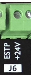
The emergency stop connector J6 is in the upper right of the V31. When the two E-Stop terminals are connected together, the red ESTP LED turns off and the controller can enable. This is a safety circuit that immediately disables the system when the circuit is broken.
J6: ESTP, +24V
Important: The V31 motion controller will not operate unless the Emergency Stop (E-Stop) circuit is complete.
Multiple E-Stop devices
Connect all E-Stop devices in series in the same E-Stop circuit.
In a series circuit, any open contact opens the entire E-Stop circuit.
If you need specialized safety circuits, contact support.
Adding an E-Stop button to the V31
Use an E-Stop button that does not require its own supply voltage.
This type is often called a "voltage-free" or "dry contact" E-Stop.
If the E-Stop button requires a supply voltage
Wire the E-Stop button to a relay input.
Use the relay output contacts in the E-Stop circuit.
Ask a qualified electrician to design and verify this wiring.
V31 E-Stop input mapping
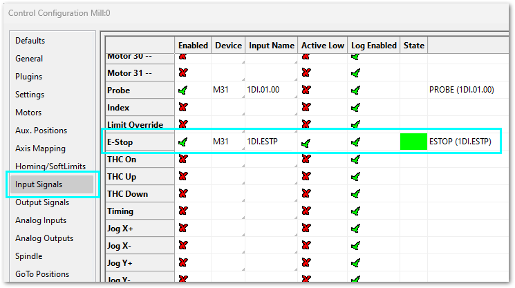
The Emergency Stop input is mapped to V31 1DI.ESTP.
Open Configure > Control and click the Input Signals tab.
Scroll down the input signals to the E-Stop signal.
When configured correctly, opening the E-Stop terminals disables the system.
The system operates only when the E-Stop circuit is closed and healthy.
Tip: The most effective E-Stop circuit carries 24 VDC the whole time the machine is enabled. If someone presses the E-Stop button, or a wire is cut, the machine is disabled. Any event that removes the 24 VDC disables the machine. When mapping the V31 input to the MachPro signal, set that input as Active Low. When the input goes low (24 VDC removed), the E-Stop signal goes high and the machine disables.
Configure the emergency stop circuit before you use hardware enable or drive enable.
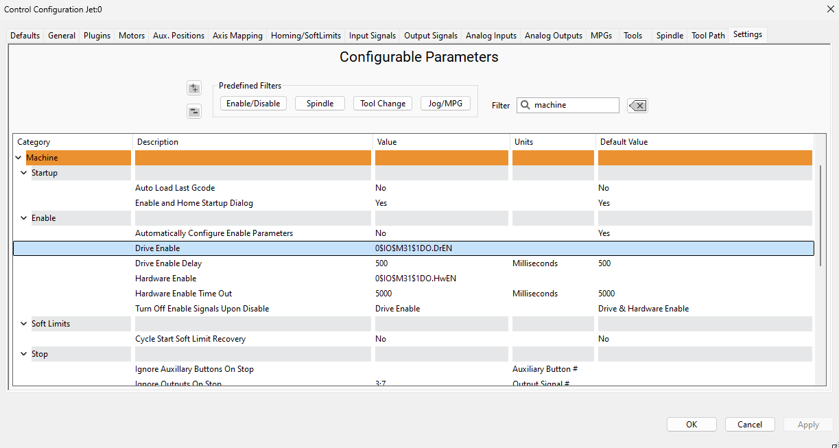
The V31 includes two control circuits: hardware enable and drive enable. These circuits stay inactive until the E-Stop circuit is configured. Use the default settings unless your application requires changes.
Accessing the enable settings
Open Configure > Control.
Select the Settings tab.
Available options
In the Settings tab, you can:
Set the delay between hardware enable and drive enable.
Choose which outputs turn off when the system disables.
I/O diagnostics
The V31 has a rich set of diagnostics.
Each input and output on the V31 has an associated LED.
The V31 Diagnostic screen shows the status of all I/O at the motion controller level (click Diagnostic > V31).
The MachPro Input Signals screen shows the state of all enabled signals in the State column (click Configure > Control, then Input Signals).
The MachPro Machine I/O screen also shows the state of all mapped I/O (click the Service tab, then the Machine I/O tab).
While you wire and map I/O signals, confirm that each port changes correctly at the V31 (its diagnostic LEDs) and in MachPro.
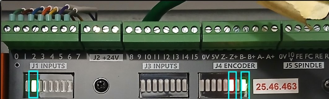
V31 diagnostics
Input pin 1 is active – 1DI.01.01
The E-Stop is active – 1DI.ESTP
There is power to the board.
The blue CPU LED blinks when the CPU is active.
Configure the dedicated network interface (J20)
The V31 motion controller connects to the control computer through a static-IP Ethernet connection.
Follow the Microsoft guide to manually set your network adapter to communicate with the V31: Microsoft Instructions: Manually Configure IPv4 Settings. Scroll to the bottom and expand the section titled "To specify IPv4 settings manually." Then:
Set IP address to 192.168.208.10
Set Subnet mask to 255.255.255.0
Save the settings and close the window.
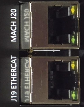
Connect the MACH J20 port to the dedicated network port on the control computer.
J20 MACH (top) to the PC · J19 ETHERCAT (bottom) to the drives
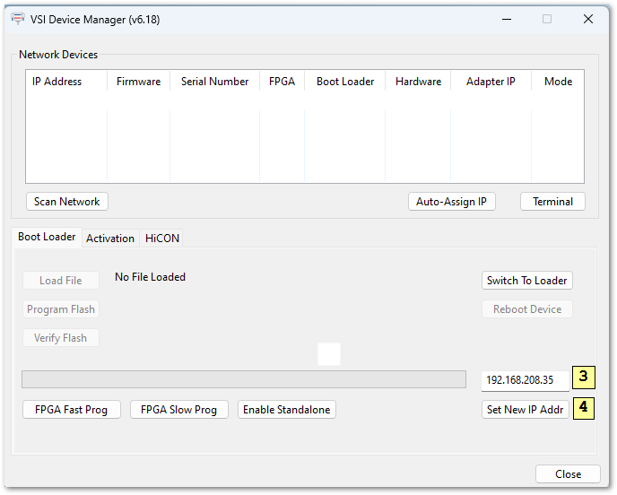
The V31 IP address (192.168.208.35) and the computer adapter IP (192.168.208.10) are pre-configured if you purchase both a CNC control and the V31.
Resetting the IP address on the V31
Verify that the V31 has 24 VDC power.
Verify that the V31 and computer are connected with an Ethernet cable.
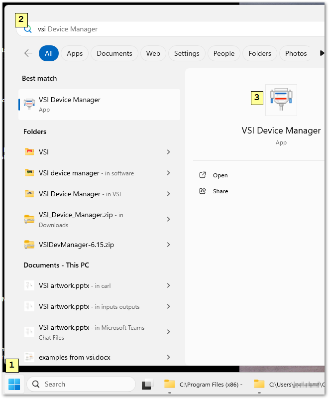
Open the VSI Device Manager software. You should see its icon on your Windows desktop.
If not, click the Windows Start button and search for VSI.
The VSI Device Manager appears as one of the windows below.
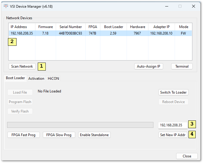
Click Scan Network.
Click the device that the scan locates. Its current IP address shows on the line at the top and in an editable field in the lower right corner. If no device appears in the list, still follow steps 3 through 6.
Enter 192.168.208.35.
Click Set New IP Addr.
Click Close.
Close MachPro, power-cycle the enclosure and restart MachPro. This ensures all network and software changes take effect.
2. Axis Setup
V31 motion controller
All of the drives and external I/O are wired into the V31. The V31 uses EtherCAT and step-and-direction to control the axes.
In this section the axis drives and motors are wired, configured and calibrated for accurate motion. Once that is done, machine zero, limits, homing and fixtures are configured in Inputs and Homing Setup.
The V31 supports step-and-direction and EtherCAT devices simultaneously.
Step and direction connection and configuration (J13–J18)
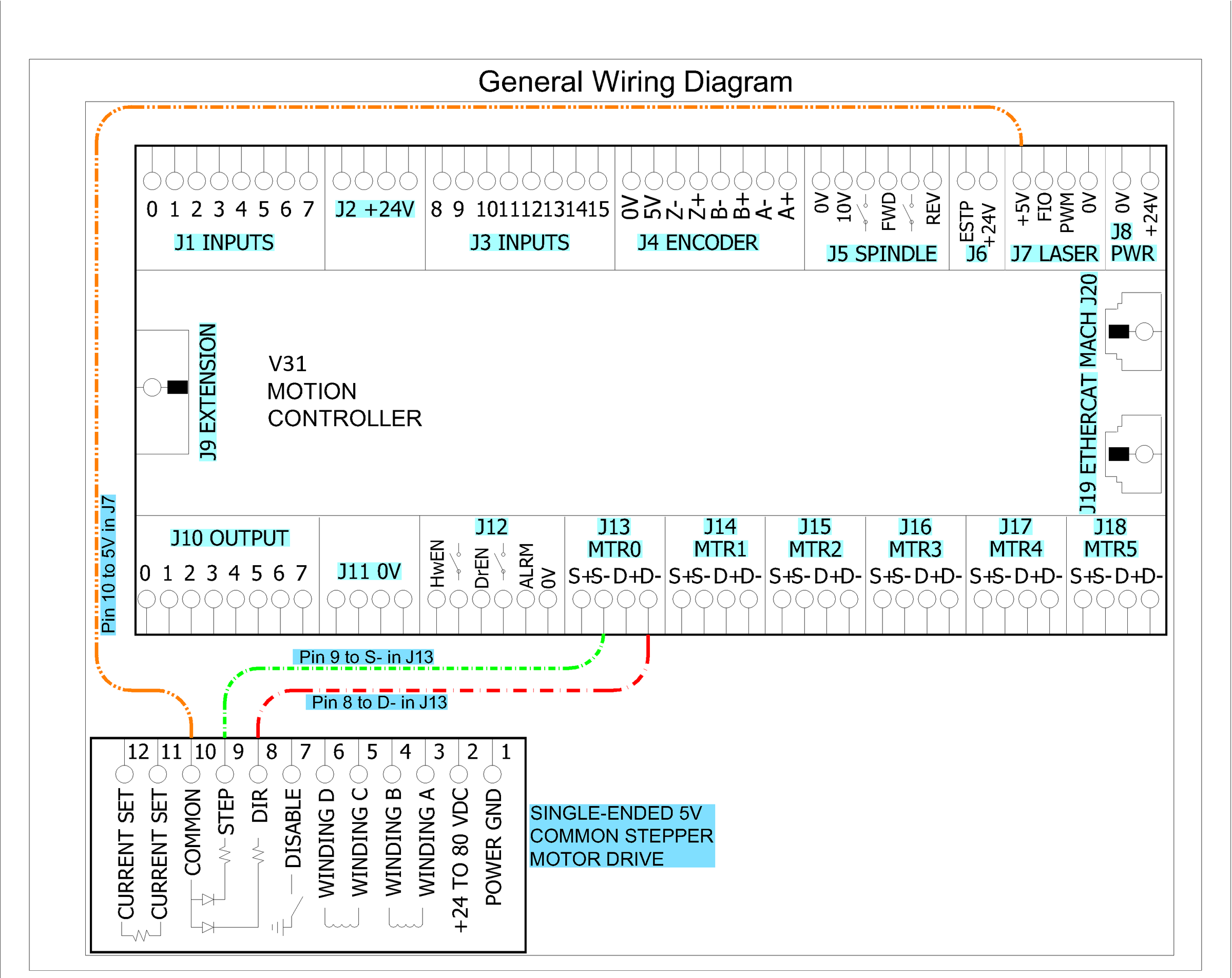
The V31 supports differential or single-ended outputs. Differential outputs use two signals for step (S+ and S-) and two for direction (D+ and D-). Single-ended uses one signal each for step and direction.
Note: The V31 does not power or drive motors directly. It supplies control signals to a drive, which powers and controls the motor.
Motor Drives
Stepper Channels
6 motors
Step and Direction Axis Control
5 VDC Single Ended and Differential
Connection
Terminal Blocks
Max Pulse Speed
1.6 MHz
J13–J18 (MTR0–MTR5): S+ S- D+ D-
If you use step and direction, wire the drives to J13–J18.
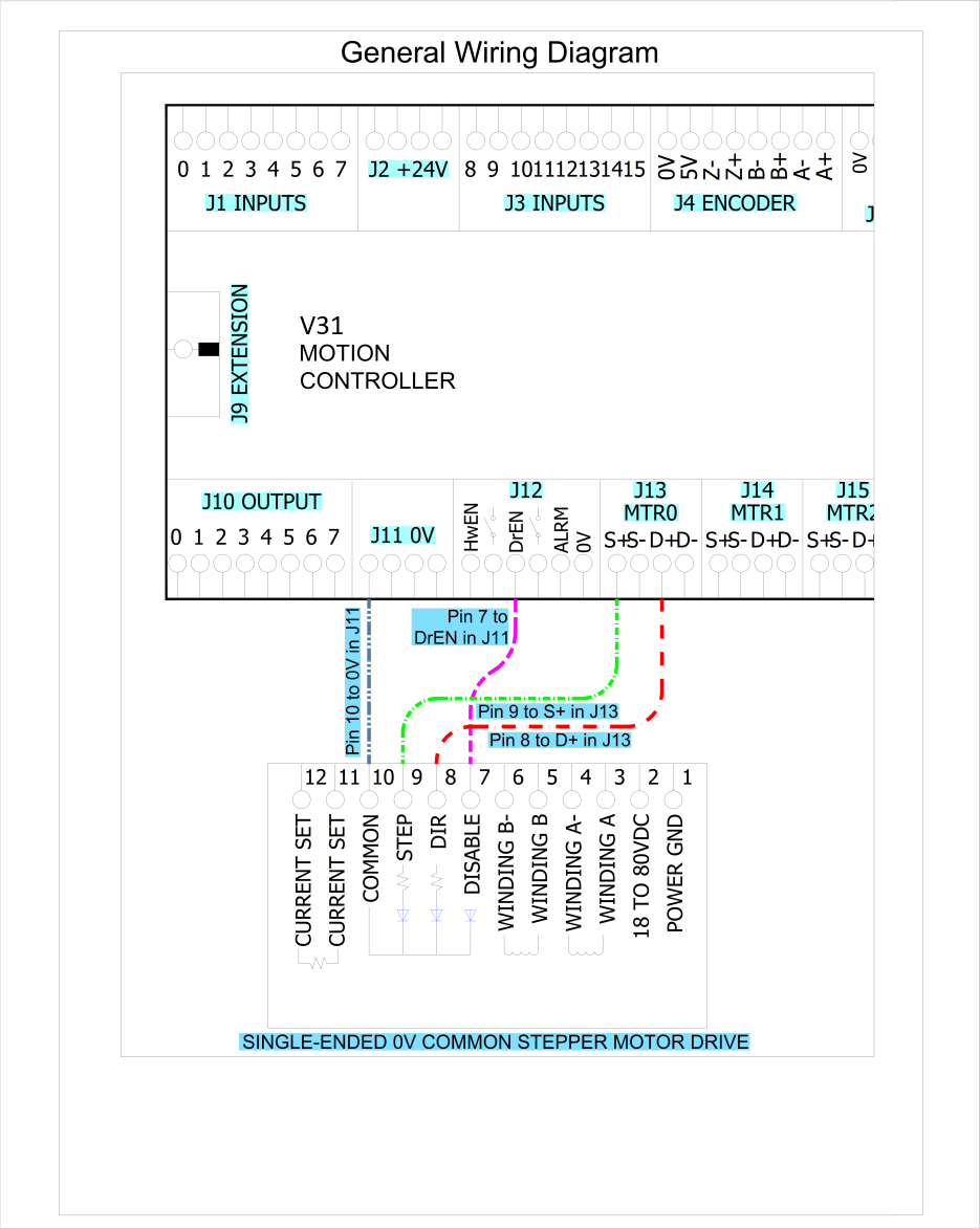
Connect to a single-ended drive input, 0 VDC common
Single-ended 0 V common drive (example: Gecko G203V)
Use this when
The controller has true differential (RS-422) step/dir outputs.
Why: S- and D- are the inverted, actively driven outputs of the differential pair. If you tie them to 0 V, you can short an output or distort the signal. This can cause missed steps or faults.
Connect to a single-ended drive input, 5 VDC common
Connect to a differential (RS-422) drive input
Use this when
The controller has true differential (RS-422) step/dir outputs.
In most differential interfaces a separate 0 V wire is not required, because the receiver measures the voltage difference between "+" and "-".
If the drive manual specifies a signal ground, shield drain or COM connection for noise control, connect it as specified.
If the drive manual does not require a 0 V connection, do not connect it. Do not use S- or D- as a ground.
Notes
Use twisted pairs: S+ with S-, and D+ with D-.
If you use a cable shield, bond it per your grounding standard and the drive manual (usually at one end).
If you have a dual-channel (2-motor) stepper drive, contact Vital Systems support for the correct configuration.
Step and direction plugin configuration
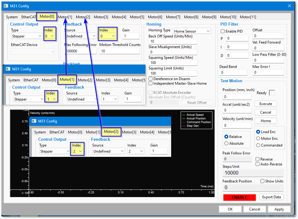
The V31 default motor configuration works for step-and-direction systems. If you add motors beyond Motor5, the Control Output Index must match the motor number.
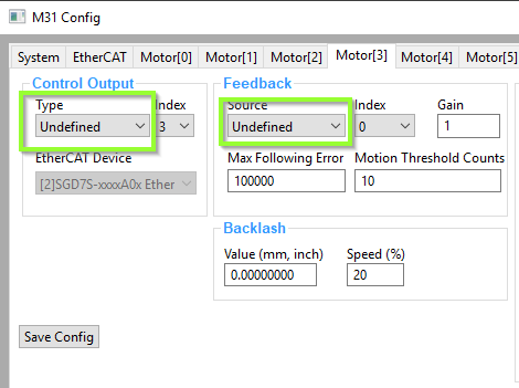
All unused motor tabs must have Control Output and Feedback Source set to Undefined.
For step and direction, set the Feedback Source Index on all tabs to 0.
EtherCAT network configuration (J19)
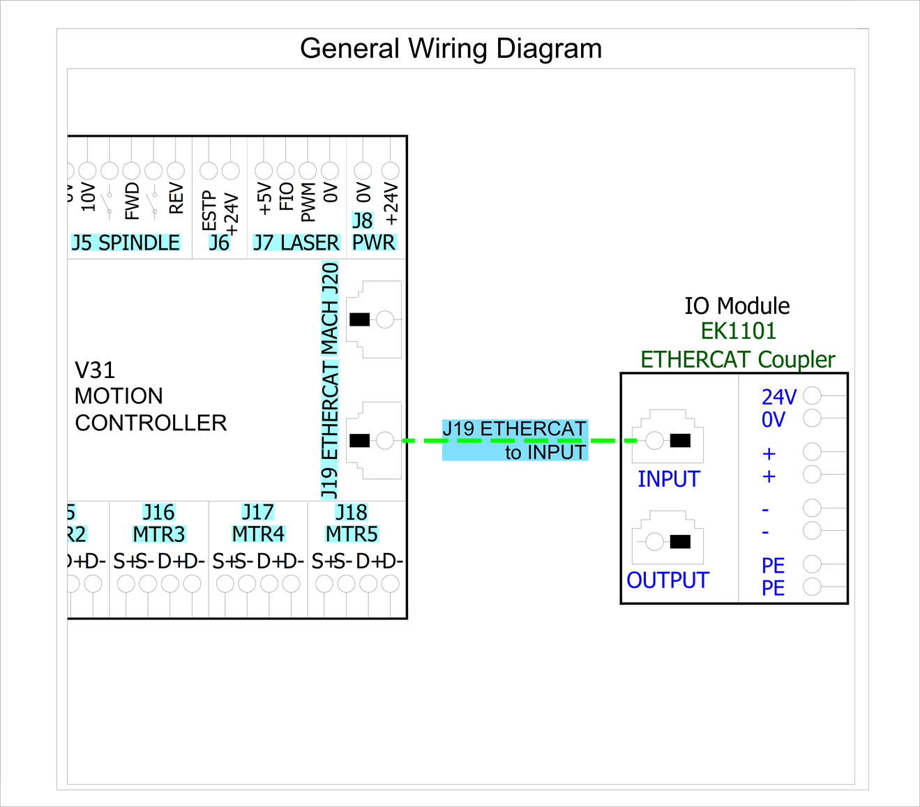
The V31 uses a standard EtherCAT physical layout. The computer connects via Ethernet to J20. J19 connects to the EtherCAT devices in a chain.
Put servo and stepper drives first in the EtherCAT chain (closest to the controller).
Put I/O devices and safety relays in the middle.
Put VFDs last (at the end of the chain). VFDs make electrical noise, and keeping them last lowers interference.
Use shielded network cable for all EtherCAT devices.
Cable length: keep each cable between 1 foot and 100 meters (about 0.3 m – 100 m).
Good cable management: keep cables neat, do not bend them sharply, and separate network cables from high-power lines when possible.
Load the EtherCAT configurations
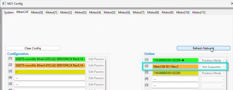
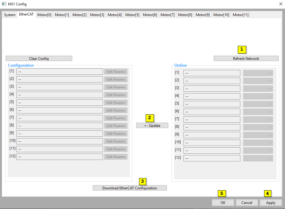
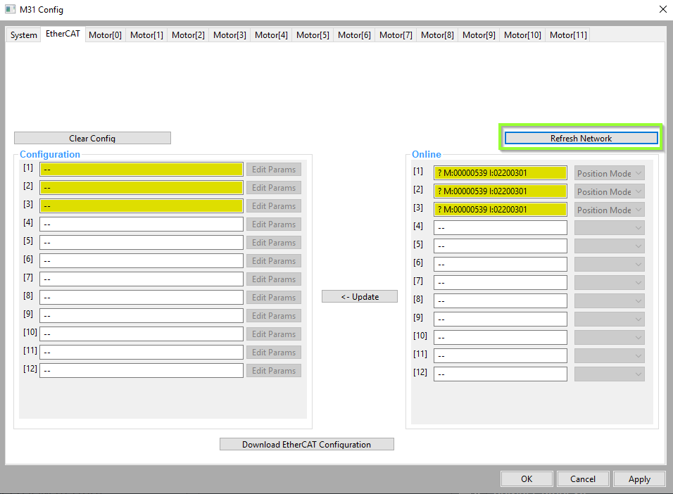
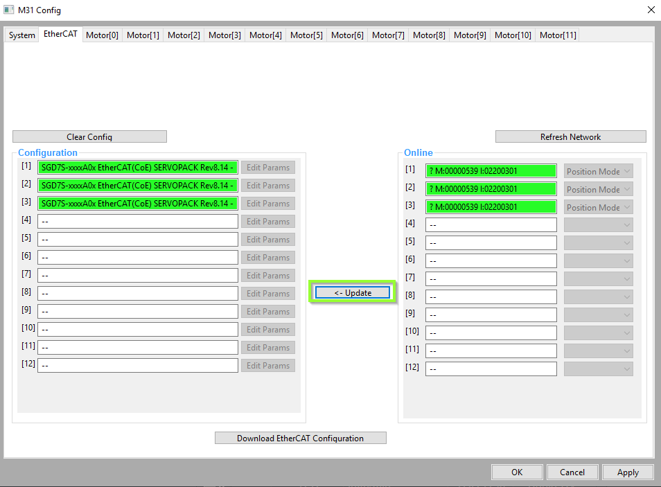
Open Configure > Plugins > V31 and select the EtherCAT tab.
You may need to refresh the network several times to retrieve all of the information.
If any device reports a status of Unsupported, contact Vital Systems support (see the end of this manual). See the list of MachPro-compatible EtherCAT Devices.
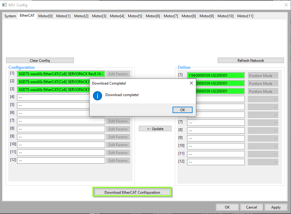
After downloading the configuration, close the Config window and restart MachPro so all configurations load.
EtherCAT drive configuration
Before calibrating EtherCAT servos, you must know your motor resolution and cap it at 17 bits, or 131,072 counts per motor revolution. This is the maximum counts per revolution the V31 supports.
17-bit resolution
Motion based on 17-bit encoders is accurate enough for most CNC systems, and it lets you choose from a wide range of servo drives and motors. However, the drives must be configured to output 17-bit encoder data even if they support a higher count. This is a common servo drive setting and may be listed as Drive Ratio, User Parameter, Encoder Output Resolution or Edge/Pitch.
Yaskawa Sigma5 and Sigma7 drives use parameter PnB02 set to 8 to change their output to 17 bit.
Each drive manufacturer has its own way to set the number of pulses reported per motor shaft rotation. Make sure every drive you plan to use with the V31 can be configured for 17-bit output.
Count
Bits
Conversion
Result
less than 131,072 (stepper drives)
less than 17
none
use the maximum resolution of the drive
131,072
217
none needed
131,072
1,048,576
220
8
131,072
8,388,608
223
64
131,072
16,777,216
224
128
131,072
Example of the math (the last row, a 24-bit drive): 224 = 16,777,216 pulses per motor shaft rotation. Divide by 8, 16, 32, 64 or 128. Here 16,777,216 / 128 = 131,072, which is the target. So for a 24-bit drive, find the drive parameter where you can enter 128 so the drive sends 131,072 pulses per rotation to the V31.
Checking resolution
How many bits is your drive sending to the V31? This is easiest when the motor is not mounted on the machine.
Power up the system and MachPro, but leave MachPro disabled so the motors can be turned by hand.
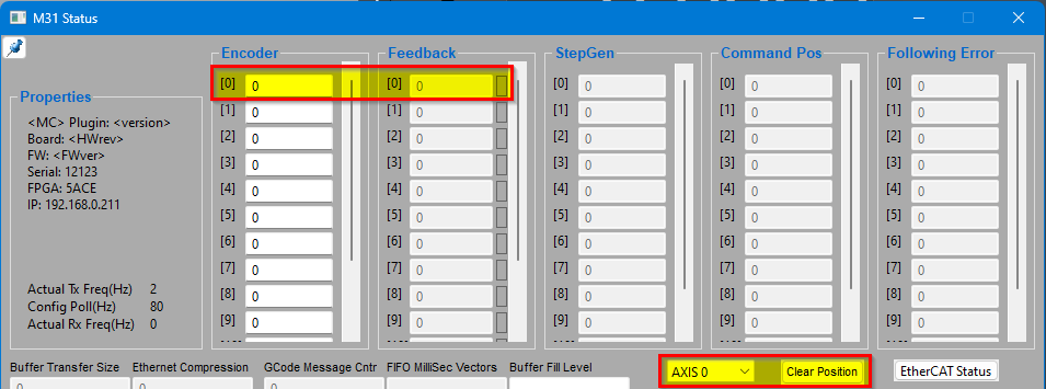
Open Diagnostic > V31.
Select the axis you are checking and clear its position data. In the example above, Axis 0 is selected. Pressing Clear Position zeroes the feedback value.
Rotate the motor shaft by hand one full turn and note the feedback value. A stepper motor may show about 10,000. A servo motor should show a number close to one in the first column of the table above.
If it is more than 131,072, reconfigure the drive so that one rotation of the motor shaft produces approximately 131,072 pulses.
When all drives use 17-bit resolution, save and close all open windows, then close MachPro.
Configure individual EtherCAT motors
After restarting MachPro, open Configure > Plugins > V31 and select the Motor[0] tab. The example below shows Motor[0] configured as an EtherCAT drive connected to a Leadshine [1]L7N(COE) drive.
Select EtherCAT Drive as the Control Output Type.
Set the Index to 0.
Select the first EtherCAT drive for Motor[0].
Select ECAT Feedback as the Feedback Source.
Set the Index to 0.
Select the Homing configuration you are using for this motor.
Each motor has a Control Output SubID and a Feedback Index. By default, leave these set to 0 for all motors.
Configure multi-axis EtherCAT drives
These are not standard one-motor-per-drive devices. If you have standard drives, skip this section.
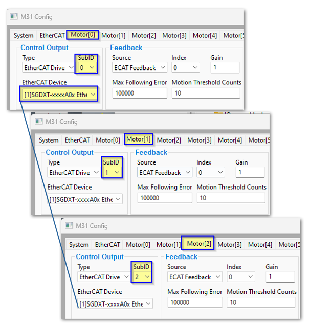
The Control Output EtherCAT Device stays the same for all motors attached to the multi-axis drive.
Set the Control Output SubID to match the motor number.
Notes
Carefully label all motors, drives and cables at the connection points before you install them. Your installation will be less frustrating.
The maximum following error is usually set to one or two rotations of the motor shaft; adjust for your system. Following error occurs when an axis is physically blocked, or when part of the axis mechanics slips and commanded motion does not produce feedback motion.
The homing section covers gantry squaring and enabling absolute encoders.
All unused motor tabs must be set to Undefined.
Enabling axes
After the drives are connected to the V31, open MachPro and enable the axes as follows.
Note: This may already be set up depending on your system. If menu options are grayed out, disable the system to allow configuration changes.
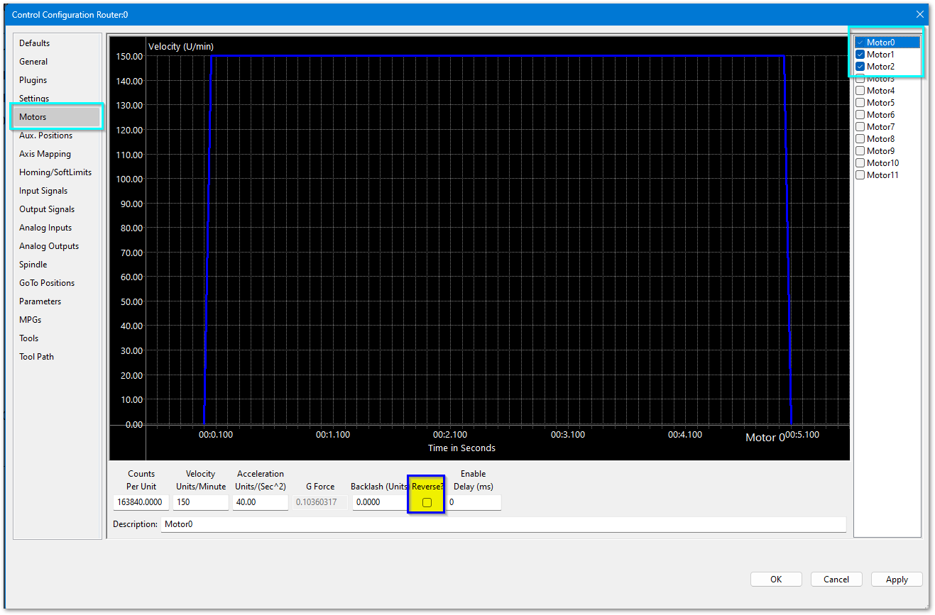
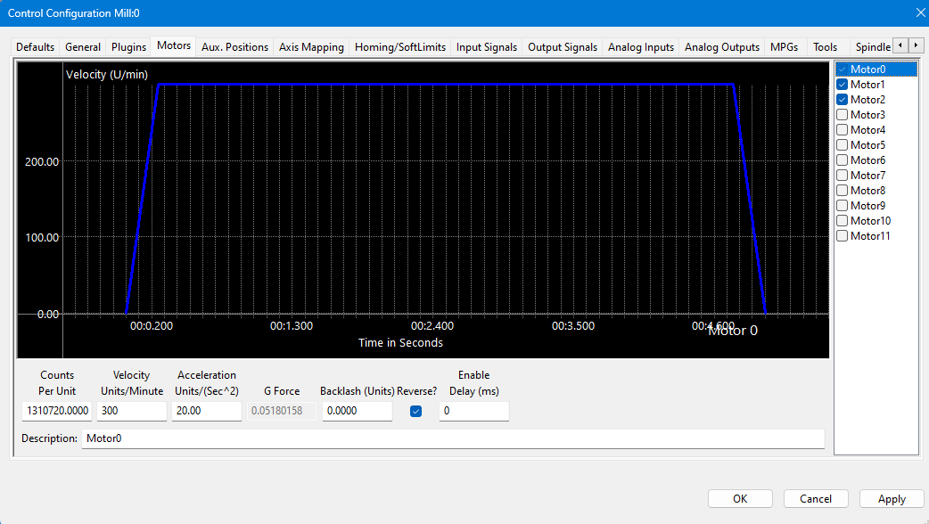
On the menu bar, click Configure > Control, then select the Motors tab.
Enable each motor to be controlled by checking its box in the right pane. In the example below, motors 0, 1 and 2 are enabled.
To test motor direction, press Apply and OK to save and close.
Click the flashing red Enable button in the lower left of the screen to enable the system.
Use your pendant, the panel jog buttons or the on-screen jog buttons to carefully test each axis direction.
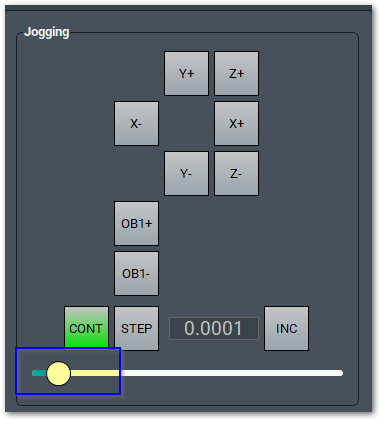
Move the jog rate slider almost all the way down for this test. Be very careful with axes that have master and slave motors: because of the gearing, they usually rotate in opposite directions from each other.
If a motor moves the wrong direction, reverse it in the Motors tab:
Click Configure > Control, then the Motors tab.
Check Reverse? for each motor that needs to be reversed.
Press Apply to save the changes.
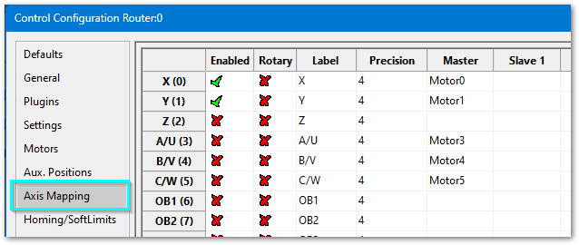
Select the Axis Mapping tab. Associate the enabled motors with the correct axis. In this example Motor0 is the X master, Motor1 is the Y master, and Motor2 is not mapped to an axis (in this EtherCAT system, the VFD/spindle is Motor2 and is not used for axis movement). No slave axes are configured.
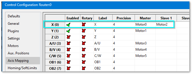
If an axis has two motors, such as a gantry, one motor is the master and the second is the slave. In the Slave column, select the slave motor. In this example X has Motor0 as master and Motor2 as slave. The Homing section links to gantry setup.
Press Apply and OK to save and close.
Carefully test jogging.
If you have been running the motors on a test bench, now mount them on the machine in their running configuration.
WARNING: The machine can be crashed very easily at this point. Calibrate the axes and configure the limits before any significant motion.
Axis calibration
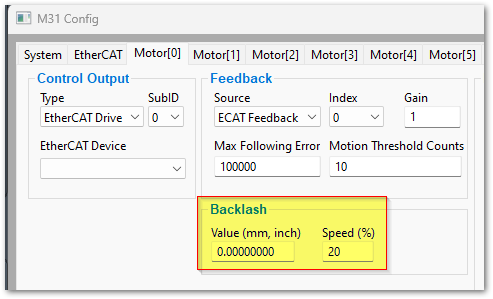
Before calibrating, set the backlash value to 0 for each axis. Open Configure > Plugins > V31 and select each motor to check the backlash settings.
Go to Configure > Plugins > Machine Calibration and select the type of calibration:
Manual – Calculates the axis by comparing distance traveled with distance commanded. See Manual calibration. Very accurate when you do not know all of your hardware specifications.
Automatic – Calibrates the axis from your system's specifications. Most accurate when you have all of your hardware specifications.
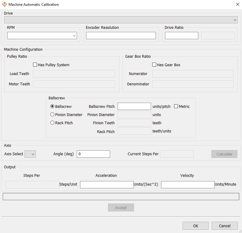
Automatic units calibration
Automatic calibration needs all the details of your motor and axis hardware. If you cannot find this information, use Manual calibration.
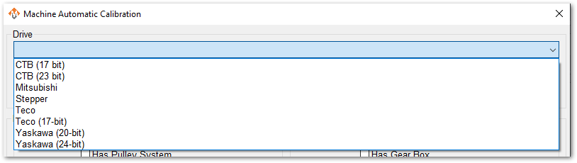
Select the drive that most closely matches yours. If there is no exact match, select by encoder resolution bits.
Select the max motor RPM.
Enter 131,072 for Encoder Resolution. For a stepper drive, or a drive under 17 bits, enter the actual resolution per rotation. To verify, see Checking resolution.
Enter 1 for the drive ratio.
If this axis uses a pulley, check that box and enter the tooth counts for the load side and motor side.
If there is a gearbox, check that box and enter the ratio.
The axis has either a ballscrew or rack-and-pinion. Select the type and complete the open fields.
Select the axis to calibrate.
Leave Angle at 0 degrees.
Press Calculate.
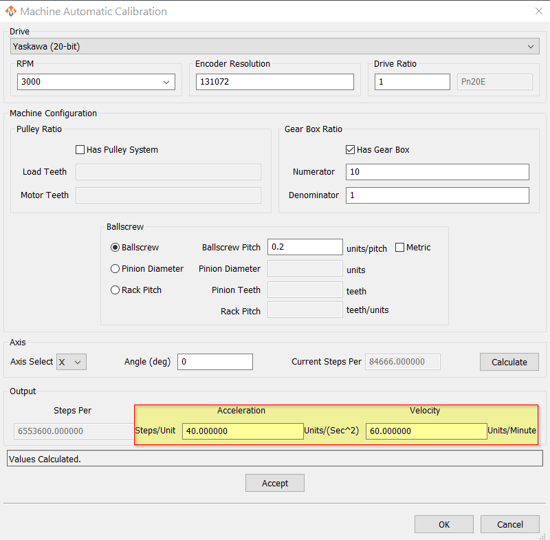
Compare the current steps value with the proposed values. You may change values and recalculate.
When ready, Accept the new steps-per value. The velocity and acceleration are calibrated maximum values based on the parameters you entered.
During operation, rapid rates can be reduced with on-screen controls.
Set acceleration to the highest value that gives smooth motion without over-torque errors, shaking, rigid motion or jolts. Acceleration that is too slow increases cycle time per part.
Repeat for each axis. Press OK and restart MachPro to save the calibration settings.
This is an example of a simple X axis that has been calculated and is ready to be accepted. Velocity and acceleration are also calibrated by this process; we recommend accepting them. They are maximum values. Click Accept.
Verify that each axis moves the distance you command.
Manual calibration
This tool compares commanded movement with measured movement and updates the MachPro steps-per-unit value. For best accuracy, use the longest distance you can measure accurately.
Select the axis to calibrate.
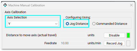
Select a calibration method:
Jog Distance – for the initial calibration. You control the movement distance and speed.
Commanded Distance – to verify or fine-tune the calibration.
Calibrate an axis with Jog Distance
Prepare the axis
Open the Axis Selection list and select the axis.
Measure and mark the longest distance you can measure accurately on the axis.
Click Enable and make sure the indicator turns green.
Jog the axis to the first mark.
Record the movement
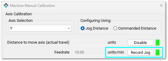
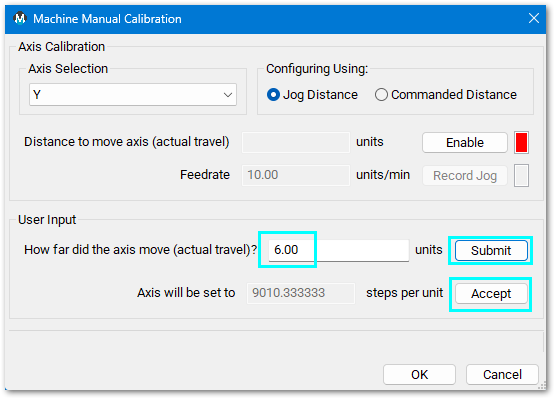
Click Record Jog and make sure the indicator turns green.
Jog the axis to the opposite mark.
Click Record Jog again and make sure the indicator turns red.
Update the calibration
Measure the actual distance the axis moved and enter it.
Click Submit, then Accept.
Make sure the lower section of the window clears and the message Steps Per Unit Updated! appears.
Calibrate an axis with Commanded Distance
Prepare the axis
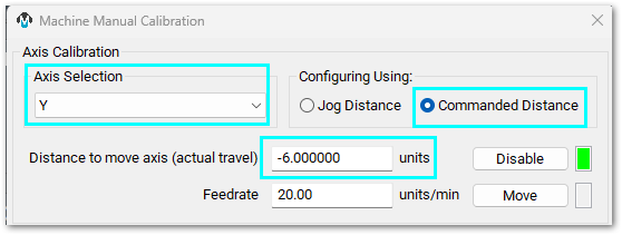
Open the Axis Selection list and select the axis.
Measure and mark the longest distance you can measure accurately on the axis.
Click Enable and make sure the indicator turns green.
Jog the axis to the first mark.
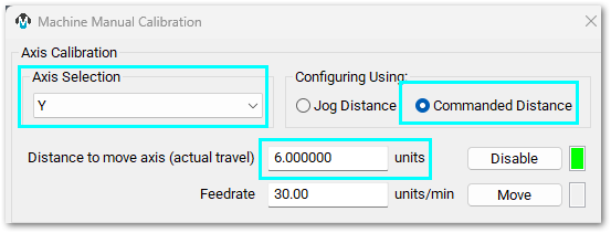
Enter the distance to the opposite mark, with the correct sign (+ or −) for the direction.
This example uses the Commanded Distance test to verify the Jog Distance calibration of the Y axis.
Run the test
Click Move.
Wait for the axis to stop.
Compare the axis position with the opposite mark.
If the axis stops at the mark: enter the commanded distance, click Submit, and confirm the status bar shows The distances moved were the same. Steps per unit will not change.
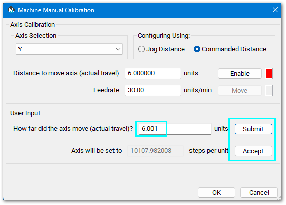
If the axis does not stop at the mark, measure the actual distance it moved.
Update the calibration
Enter the measured distance.
Click Submit, then Accept.
Make sure the lower section of the window clears and Steps Per Unit Updated! appears.
Axis calibration is necessary for accurate machine movement. Verify that each axis meets your accuracy requirements before you continue. The remaining steps depend on correct calibration; if you change calibration later, configure the affected settings again.
Configure velocity and acceleration
Use this procedure to adjust the maximum velocity and acceleration for each motor. The Automatic Axis Calibration tool can calculate initial values; use this procedure to tune them for your machine.
WARNING: Do not use high velocity or acceleration values until homing and limits are configured. Incorrect values can cause machine damage.
Open the motor settings
Open Configure > Control.
Select the Motors tab.
Click the motor name in the right pane. Click the word to highlight and select it; the checkbox only enables or disables the motor.
Set velocity
Velocity controls the maximum rapid speed for the motor.
Select the motor.
Set Velocity to a conservative value and click Apply.
Test the axis with a short jog move.
Increase the velocity in small steps.
Stop increasing it when motion becomes rough, inaccurate or unsafe.
The practical maximum velocity depends on motor speed, drive capability, counts per unit, axis travel length, machine rigidity, load inertia and required cut quality.
Set acceleration
Acceleration controls how quickly the axis reaches the commanded speed. It also controls deceleration.
Select the motor.
Set Acceleration to a conservative value and click Apply.
Test the axis with short jog moves.
Increase the acceleration in small steps.
Stop increasing it if the axis shakes, faults, jolts or loses position.
Typical starting values: stepper motors 15–20, servo motors 30–40. These are starting points only; adjust them for the machine.
Save the settings
Click Apply before selecting another motor.
Repeat for each motor.
Click OK when all motors are configured.
If you change counts per unit later, verify velocity and acceleration again.
WARNING: No limits have been set up. DEATH, INJURY or serious PROPERTY DAMAGE can occur if the system is not operated carefully. Limits and homing are set up in the following sections.
Backlash repair and compensation
Backlash is caused by gaps between moving parts such as gears and ballscrews. It is the amount one component can move in one direction without moving the next connected part. Most mechanical systems have some backlash, even when new; if the mechanics are too tight, binding and excessive wear result. As gears and ballscrews wear, backlash increases and accuracy decreases. Ongoing testing and maintenance of the mechanical system is required to minimize backlash.
The V31 provides software backlash compensation as a short-term solution for small, stable amounts of backlash. To measure the backlash of an axis, use How To Test For Backlash.
Backlash Value (in Configure > Plugins > V31) – the backlash amount in inches or millimeters, depending on setup units. For best performance, backlash should be less than 0.0015 in. Start by entering half of the measured backlash, then test and adjust.
Backlash Speed % (in Configure > Plugins > V31) – a factor of the axis acceleration. The V31 multiplies the motor's max acceleration by this percentage. Valid values are 10–400 (0.1 to 4 times max acceleration). A common value is 20%.
Do not leave Backlash Speed at zero. The V31 will not function with a speed of zero.
All axes are now calibrated, but MachPro does not yet know the travel limits of each axis. That is configured next. Until then, be very careful when moving axes.
3. Inputs and Homing Setup (J1 & J3)
First wire the inputs and outputs to the V31. Then map the appropriate software signals to those hardware connections.
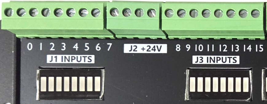
J1 inputs 0–7 · J2 +24 V · J3 inputs 8–15
Inputs: 16 (PNP Sourcing)
Voltage
16–24 VDC
Input Current Range
3–6 mA
Isolated
Yes
Wiring inputs
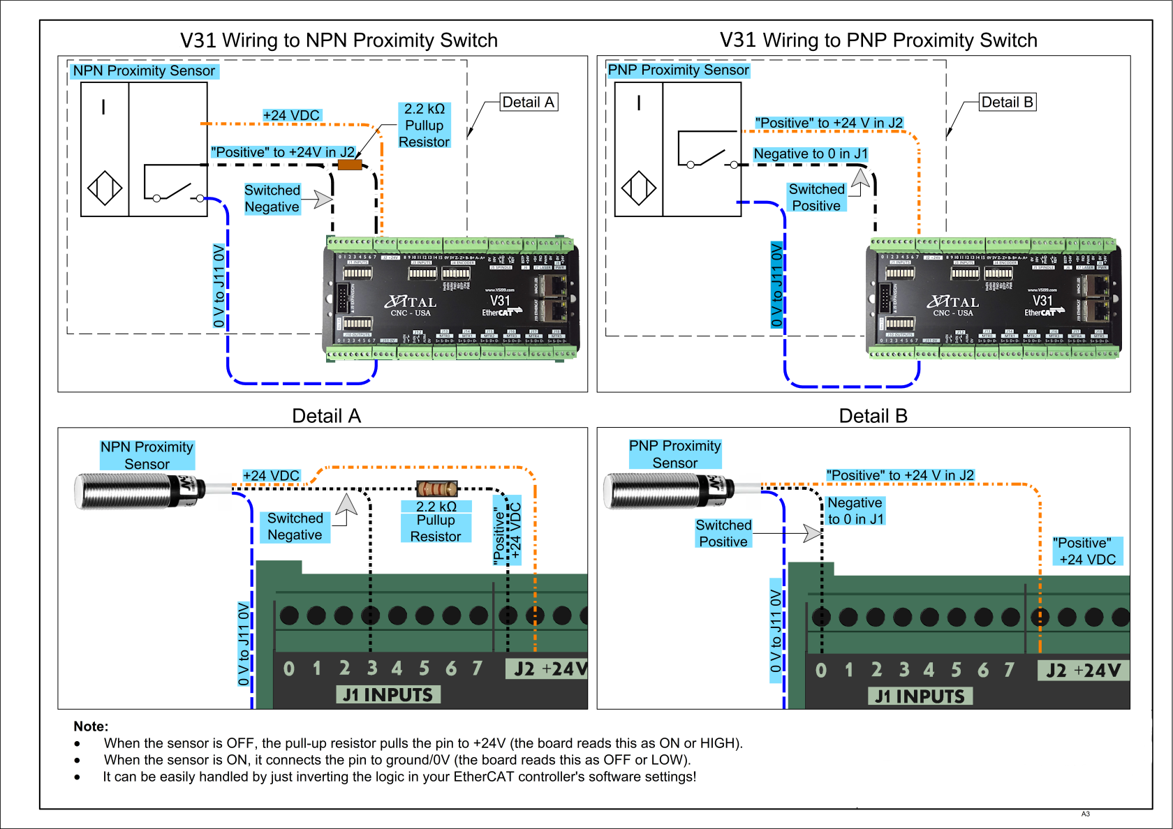
The V31 has 16 PNP inputs for limit and home switches, probes and other sensors.
Note: For the highest level of safety, wire limit switches normally closed. If a limit is tripped, or a wire or switch is damaged, the system stops motion.
To wire 24 V limit switches:
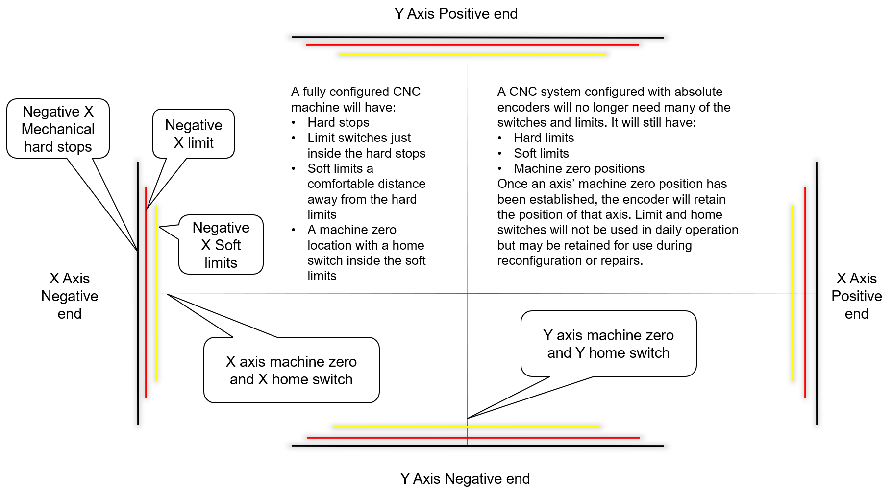
Select or install two limit switches at the ends of each axis's hard limits.
Wire the two switches in series, normally closed. If either limit trips, the circuit opens and motion stops.
I/O ports are limited; wiring the limits for an axis in series conserves ports while keeping the function.
Safety circuits often require each limit to have its own input.
Wire one side of the first switch to +24 V from the V31 (J2).
Wire the other side of the limit string into an input on the V31. Label the wires and document the I/O.
Wire a home switch on each axis to a separate input.
Tip for success: Once you understand how to wire and map inputs and outputs, use the charts in Reference Information to plan the physical wiring and software mapping.
Mapping signals
At the top of the screen, open Configure > Control.
Click the Input Signals tab.
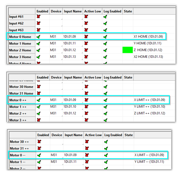
Scroll down to each motor section: Home, ++ and --.
Note the State column. It shows the current state of the signal and immediately confirms your I/O configuration. In the screen below, Z is homed.
For each signal mapping (Home, ++, --):
Enable mapping: Click the red [X] next to the signal. It turns into a green [✓], which turns the mapping on.
Device: Choose V31 from the Device list.
Input Name: Pick the input you wired (for example 1DI.01.08 or 1DI.01.09).
Active Low: If your limit switches are normally closed, click the red [X] to change it to a green [✓]. This makes the input active when the voltage goes low. Wiring normally closed is the safest method.
Description: Type the name for this axis limit (the name operators and designers use).
When all limits and home switches for a motor are done, click Apply, then OK.
Short example
Motor 0: Home, ++ and -- are enabled (green check).
All limits are wired normally closed.
V31 1DI.01.09 is used for both ++ and --.
V31 1DI.01.08 is used for the Home switch. A separate input for Home is more reliable.
Manually trigger each limit switch and make sure it disables Mach before continuing. This verifies both the wiring and the signal mapping.
Machine zero setup
The V31 supports absolute encoders through the EtherCAT interface. This feature is configured after inputs and homing are complete.
Machine zero is also called the Reference Position, Machine Home, G28 position, Home Switch Position and Machine Coordinates (0,0,0). It is the position from which the system measures all movement. You normally work with fixture (part) zero; see the operator manual for your machine type.
Danger: If limit switches are wrong or an axis moves the wrong direction, the machine can crash.
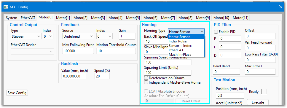
Open Configure > Plugins > V31 and select the Motor[0] tab.
The Homing Type is set in the Homing section. There are five options:
Home Sensor – The simplest to understand and troubleshoot, and very reliable. We recommend home sensors even on machines with absolute encoders enabled.
Index Pulse – Homes to a particular pulse in the motor rotation. The most accurate method, but if anything changes in the motor or machine mechanics, it must be reset.
Sensor + Index – Touches the home switch, then backs off to a particular index pulse. Easier to set up, but with the same vulnerability to motor and mechanical changes as Index Pulse.
EtherCAT – Enables advanced EtherCAT communication with the drive to use the drive's own homing methods. Contact support if you need this feature.
Mach In-Place – Defines machine zero as the axis's current location.
Select the homing type for each motor, then press Apply and OK.
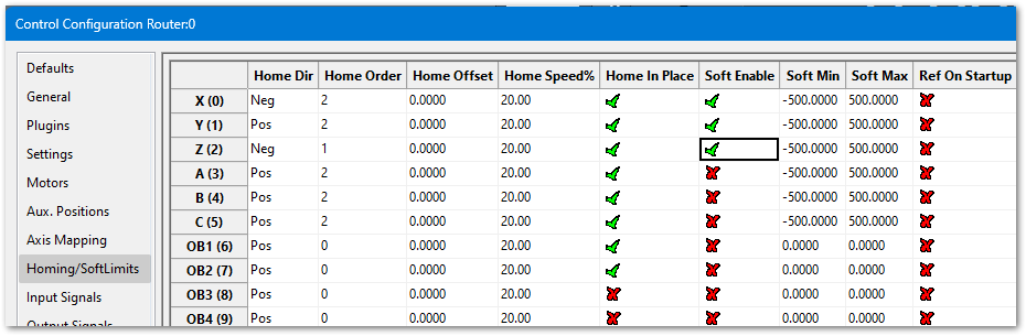
Open the settings: click Configure > Control, then the Homing/SoftLimits tab.
Columns
Home Dir: The direction the axis moves to find home, positive or negative.
Home Order: The homing order (1 = first, 2 = second, etc.). Tip: Z is often set to 1 so it moves up first and stays out of the way.
Home Offset: The machine coordinate value MachPro assigns to the axis when homing finishes.
Home Speed%: How fast the axis homes, as a percent. 20% is the usual maximum for best results; slower speeds help prevent over-travel. You can jog quickly near home before homing to save time.
Home In Place: Set this based on your hardware in the motion controller config. It is used with absolute encoder systems, where the V31 homing type must be set to Mach In-Place. If you do not use this method, deselect it for each axis.
Soft Enable: Deselect if you will not use soft limits on this axis.
Soft Min: The most negative position allowed on this axis. Soft limits are set in the next section.
Soft Max: The most positive position allowed on this axis.
Ref On Startup: Used on machines that rely heavily on G90 and G92.
Soft limits prevent the machine from moving beyond the configured travel range. They only work correctly after:
Axis calibration is complete.
Motor direction is correct.
Homing is configured.
The machine is homed.
WARNING: Soft limits do not replace physical limit switches. Always install and test physical limit switches.
Record the travel limits
Home the machine.
Select Machine Coordinates on the locked screen view and verify that the DRO values are orange.
Jog the axis toward the positive end of travel. Stop before the physical limit switch and record the machine coordinate.
Jog the axis toward the negative end of travel. Stop before the physical limit switch and record the machine coordinate.
Repeat for each axis.
Stay inside the physical limit switches. If the machine moves outside them, the soft limit values will not protect the machine correctly.
Enter the soft limit values
Click Configure > Control and select the Homing/SoftLimits tab.
Find the axis, and enable Soft Enable.
Enter the most positive recorded value in Soft Max and the most negative in Soft Min.
Repeat for each axis, then click OK.
Test the soft limits
Enable soft limits.
Jog each axis slowly toward the positive soft limit and verify motion stops before the physical limit switch.
Jog each axis slowly toward the negative soft limit and verify motion stops before the physical limit switch.
Load a sample G-code file and check the toolpath display.
Note: When a G-code file is loaded, the toolpath display shows the soft limits as dashed lines. If any part of the toolpath is outside the soft limits, check your file.
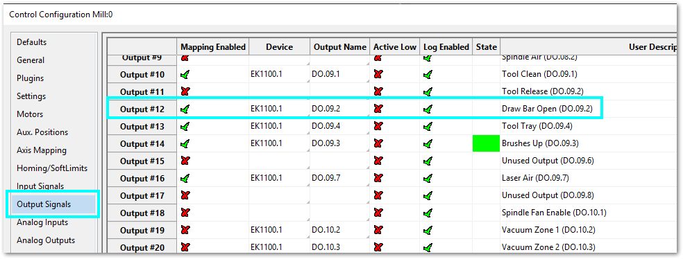
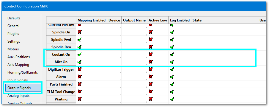
On the menu bar, click Configure > Control and select the Output Signals tab.
Select the motion control Device and Output Name.
Add a User Description, which shows on the Service tab's I/O dashboard.
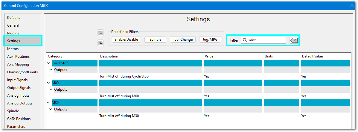
On the left menu bar, select the Settings tab.
Filter for Mist or Flood and adjust the settings for your system.
Feature
ON M-Code
OFF M-Code
Mist
M7
M9
Flood
M8
M9
5. Spindle Setup (J5)
J5 SPINDLE: 0V · 10V · FWD relay · REV relay
Configure the VFD for the spindle motor
A VFD (Variable Frequency Drive) controls the speed of the spindle motor. Set the VFD to match the motor's electrical ratings:
Rated voltage
Rated current
Rated speed (RPM range)
Use the values from the VFD manual and the spindle motor manual. Do not guess these values.
Spindle control options on the V31
The V31 controls the spindle with either 0–10 VDC or EtherCAT. EtherCAT is recommended if your hardware supports it; it provides more control and access to advanced VFD functions. Use your VFD manual to determine which control methods it supports.
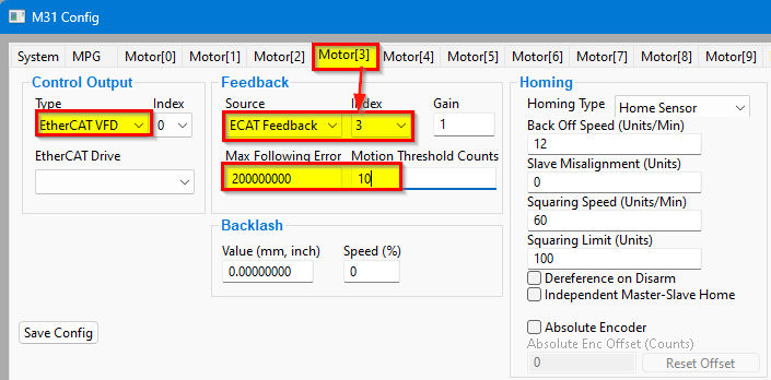
EtherCAT spindle configuration
Open Configure > Plugins > V31.
The feedback index is the same as the motor number (in this case 3). Set the Max Following Error very high, as it is not meaningful for a spindle.
Turning on the spindle
In addition to the screen controls, the spindle can be controlled with M-codes:
M-Code
Function
M3
Clockwise
M4
Counterclockwise
M5
Stop
Encoder feedback (J4)
J4 ENCODER: 0V 5V Z- Z+ B- B+ A- A+
Quadrature Encoder Channel: 1
Connection
Terminal Blocks, 5 VDC Differential
Max Frequency
1.6 MHz
Refer to the documentation for your VFD and spindle motor for spindle encoder connections.
0–10 VDC configuration
Analog spindle control uses three signals:
Forward rotation signal
Reverse rotation signal
0–10 V analog speed signal
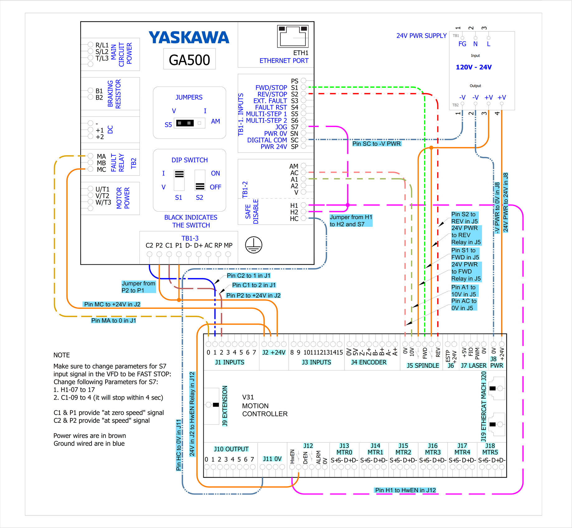
The V31 uses forward and reverse relays (dry contacts on J5) to control spindle rotation direction. The drawings below show 0–10 VDC connections to a Yaskawa GA500; your VFD manual should have similar documentation.
Analog spindle voltage adjustment
On the Systems tab of the V31 plugin, the spindle voltage can be adjusted by changing the percentage (10–200%). Most systems will not need this. If the voltage is not close enough, calculate the adjustment with:
Analog Spindle Scale % = Commanded Voltage / Actual Voltage × 100
Many advanced features, such as periodic oiler control, are configured in the Mach settings. Go to Configure > Control and open the Settings tab. Settings contains custom options for the control, including dialog options, lube system, tool measurement/offsets and tool changer options.
J7 LASER provides +5V, FIO, PWM and 0V terminals for a laser module. Wire and configure it according to your laser module's documentation, and contact Vital Systems support for the current firmware support status of this port.
Expansion (J9)
J9 is the expansion header for Vital Systems add-on boards. Pin 1 is marked with ▲ on the board.
Print this page and fill in the Signal and Use columns while planning your wiring.
Signal
V31 Junction
Input Name
Use
J1
1DI.01.00
J1
1DI.01.01
J1
1DI.01.02
J1
1DI.01.03
J1
1DI.01.04
J1
1DI.01.05
J1
1DI.01.06
J1
1DI.01.07
J3
1DI.01.08
J3
1DI.01.09
J3
1DI.01.10
J3
1DI.01.11
J3
1DI.01.12
J3
1DI.01.13
J3
1DI.01.14
J3
1DI.01.15
Signal
V31 Junction
Output Name
Use
J10
1DO.01.00
J10
1DO.01.01
J10
1DO.01.02
J10
1DO.01.03
J10
1DO.01.04
J10
1DO.01.05
J10
1DO.01.06
J10
1DO.01.07
9. Troubleshooting
Test setup
If you want to test motion before installation, or are having trouble getting correct motion, do a bench test with your motors, drives and cables. This is especially helpful for setting and verifying 17-bit encoding.
It confirms you have all the cables you need.
You can verify that all motors work.
You can easily verify that your drives are set to 17 bit or less.
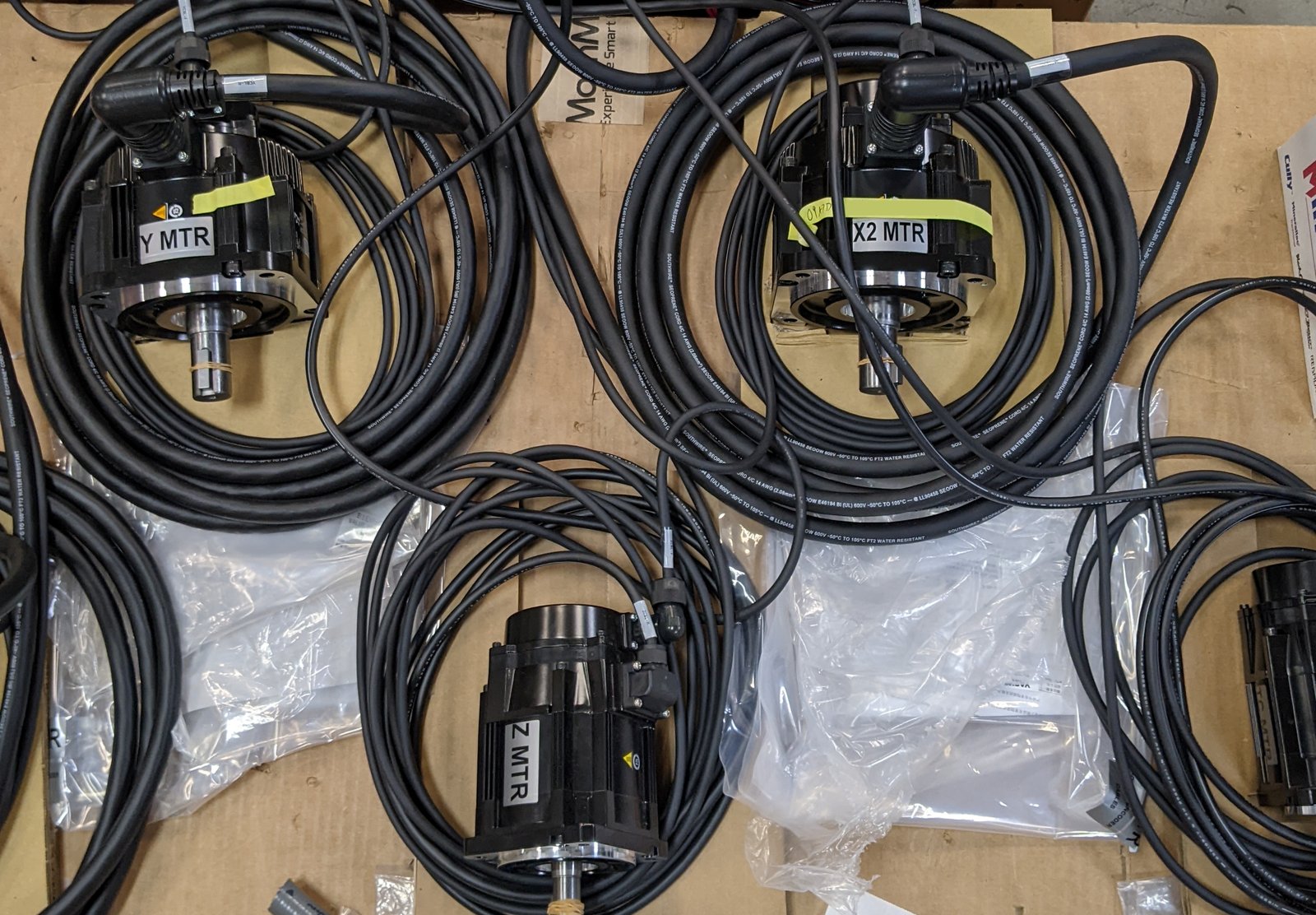
Set the motors on a stable work surface; the packing materials often work well as temporary pads. Connect all cables between each drive and motor. You may leave the motors like this until the system is ready for axis calibration, when they must be installed on the machine.
Testing axis motion
This procedure applies to step-and-direction and EtherCAT axes.
WARNING: Make sure each axis can move safely in both directions. No software limits are active during this test. If the motor is installed on the machine, the only travel limits are the physical hard stops.
Open the V31 test motion screen
Open Configure > Plugins > V31.
Select the motor to test.
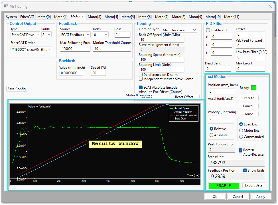
Find the Test Motion section in the lower right corner of the window.
Set the first test move
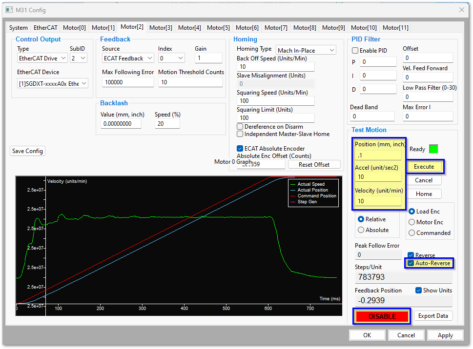
Use small values for the first test.
Set Position to 0.1.
Set Accel to 10.
Set Velocity to 10.
Select Auto-Reverse.
Click Enable in the Test Motion section.
The motor is now ready for a test move.
Run the test move
Click Execute and verify that the axis moves.
Click Execute again and verify that the axis moves in the opposite direction.
The second move reverses direction because Auto-Reverse is enabled.
Increase the test values slowly
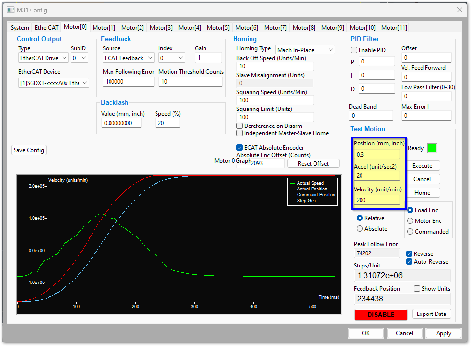
After the first test works, increase the values in small steps. Example: Position 0.3, Accel 20, Velocity 200. Click Execute and verify the motion is smooth and controlled.
Use short distances during this test. The goal is to verify communication between the V31, the drive and the motor.
Repeat the test
Repeat for each motor, and verify that for each one:
The motor enables correctly.
The motor moves when commanded, in the expected direction.
The motor reverses direction when Auto-Reverse is enabled.
The motion is smooth.
No drive alarms occur.
EtherCAT problems
The EtherCAT cables must be shielded.
Very carefully check the In/Out cabling sequence through the entire EtherCAT chain. If one or more devices is connected backwards, the EtherCAT network will power up but will not enable.
All drives must be programmed and all alarms cleared. Some drives let you clear the alarm from the front panel without clearing the internal alarm state. Close MachPro, power-cycle the enclosure, then restart MachPro.
Drives connected to the V31 must be configured for 17 bit or less. If configured for more, the system may still move, but very sluggishly.
If you see a Not Supported status next to a device in the EtherCAT tab of the Config window, contact support.
EtherCAT network troubleshooting
Close MachPro and shut down the computer.
Cycle the power on the whole machine.
Restart the computer and MachPro. Recheck whether the problem remains.
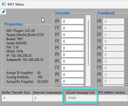
Verify that the GCode Message Cntr is still active in the Status window (Diagnostic > V31).
Verify the EtherCAT chain between drives. Disconnect the cable from drive 1 to drive 2 and refresh the network (several refreshes may be needed to fully populate the drive list).
If that works, reconnect drive 1 to drive 2 and disconnect drive 2 from drive 3. Repeat until the drive list will not populate; the chain is getting stuck at that drive.
Check the parameters you programmed into that drive.
If the list of online devices in the right column still does not populate with valid devices, contact Vital Systems support.
Network
Are the V31 motion controller and computer connected and communicating?
Make sure the Motion port on the computer is connected to the MACH J20 port on the V31.
In MachPro, open Diagnostic > V31.
The value in GCode Message Cntr should be actively changing.
If it is static or 0:
Close MachPro, power-cycle your enclosure, then restart MachPro.
Research and resolve all alerts and warnings that appear during that process.
When enabling or booting up, an EtherCAT slave device moves through four main communication states managed by the EtherCAT State Machine (ESM):
Init (Initialization) – The initial state after power-on. No mailbox or process data communication is possible. The master initializes the slave's address and communication settings. The EtherCAT master is asking each device in the chain: "What kind of device are you?"
Pre-Operational (Pre-Op) – Mailbox communication is enabled, so the master can configure SDOs (Service Data Objects), PDO (Process Data Object) mapping and other parameters. Process data communication is not yet active. The master is asking each device: "How are you configured?"
Safe-Operational (Safe-Op) – The master and slave check the configuration. Mailbox and process data communication are active, but the slave only sends input data; outputs are held in a safe state (for example, switched off). If any device has an alarm, EtherCAT will not move past this state.
Operational (Op) – The slave is fully functional. Mailbox and process data communication are active, and the master sends output data, which the slave applies.

![Motor[0] EtherCAT configuration](images/2025-12_4eqimage.png)